Search in EEW
Sunday, 17 August 2014
Saturday, 16 August 2014
Friday, 15 August 2014
Subscribe to:
Posts (Atom)
LIKE Us ヅ
Popular Posts
Blog Archive
-
▼
2014
(1164)
-
▼
August
(53)
- Typical sub-station layout
- Symbol for and structure and appearance of a thyri...
- Principle Operation of Induction Motor
- pin type Insulator
- Logic Gates Symbols
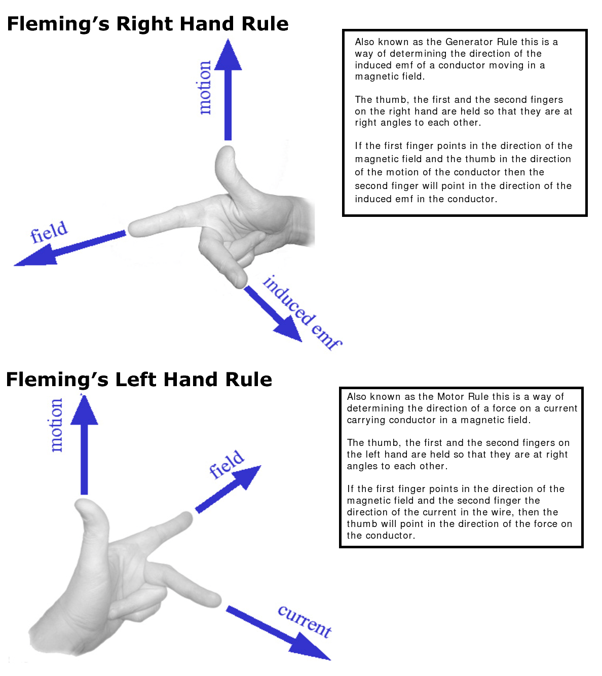
- Fleming's Right Hand Rule
- Electronics References Sheet
- Electronics References Sheet
- Correct connection of plug top
- Biomass to Electricity
- Basic concepts of SCR (Silicon Controlled Rectifier)
- Basic Components of Power System Protection
- 3 PHASE SEQUENCE INDICATOR
- Autotransformer motor starter
- Basic structure of the electric system
- timed starting of two motors
- Transmission Tower Body
- Typical Transformer Nameplate
- Schematic symbols for common electronics and elect...
- Power circuit connection of a VFD bypass contactor
- PLC wiring design
- How Amplifier Works
- Converter 12 VDC to 230 VAC or Inverter circuit di...
- Starter Coil,holding contact,and pushbutton
- Difference b w bolt, screw and stud
- Watts,Ampers,Ohms,and Volts
- Synchronous vs Induction Motors
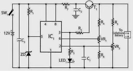
- Mobile Charger Circui
- MCB – Miniature Circuit Breaker
- Home appliances control through TV Remote Schematic
- Essential Parts of DC Machine
- Converter 12 VDC to 230 VAC or Inverter circuit di...
- Complete diagram of an off-grid solar power system
- Breadboard kits
- Selecting a Power Cable
- TYPICAL CIRCUIT-BREAKER CONTROL CIRCUIT
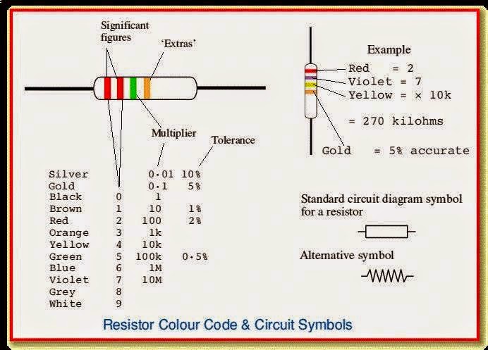
- Resistor Colour Code and Circuit Symbols
- tesla top labeled
- Generator Operation
- Symbols of AC Motors
- Dual-speed, three-phase squirrel-cage single-windi...
- Coaxial cable
- Typical Body Resistance & Current Flow
- Star-Delta and Delta-Star transformation
- power factor correction methods
- rotating magnetic field
- AC Volts Test and DC Amps Tesr
- Servo Control Parts
- Solar Energy Collector
- American Satndard Wire Gauge
- Generation, Transmission & Distribution Scheme
- Basic Electrical Symbols
- Electromagnetic Spectrum
-
▼
August
(53)
Powered by Blogger.


.jpg)


